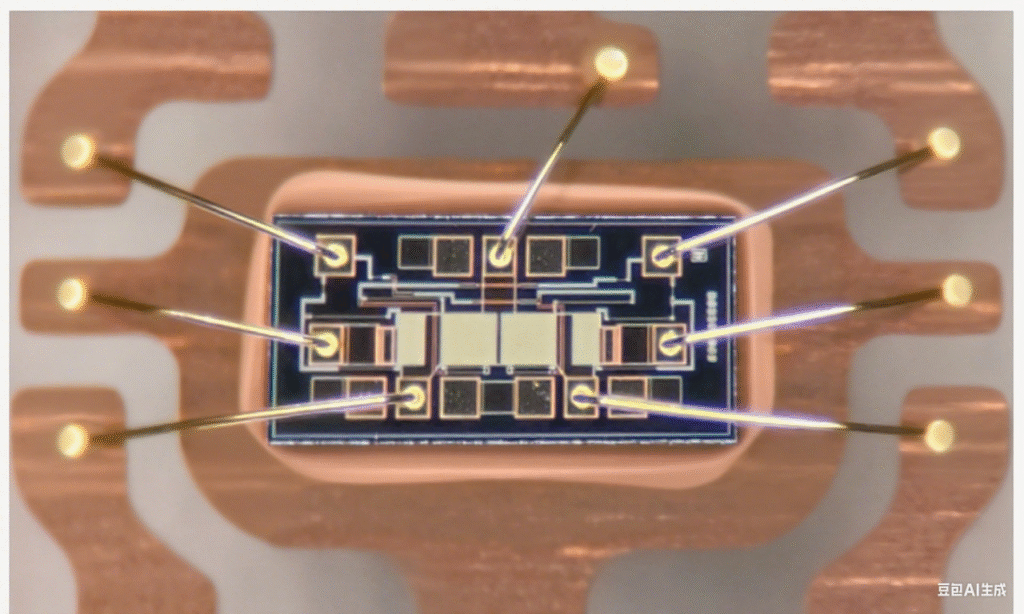
Wire Bonding Fish Tail Tear: Causes, Mechanisms, and Prevention in Semiconductor Packaging

Fish Tail Tear in Wire Bonding Process: Causes and Solutions
Definition:
In the wire bonding (Wirebond) process, fish tail tear refers to a defect where the bonding wire (commonly gold wire or copper wire) develops a tail-like tear or deformation at the ball bond or wedge bond end. This defect can significantly impact bond strength and long-term reliability. The root causes are complex, involving material properties, process parameters, equipment status, substrate conditions, and environmental or design factors.
I. Wire Material-Related Causes
- Material Purity and Composition
- Wires with excessive impurities (such as copper, silver, or iron) show reduced ductility and deformation ability. Under bonding stress, impurities can initiate micro-cracks, leading to end tearing.
- Example: Low-purity gold wire has poor fatigue resistance and is prone to local fractures under bonding pressure or thermal cycling.
- Wire Surface Condition
- Oxidation Layer: Exposure to humidity or high temperatures during storage/transport may form oxide films (e.g., Au₂O), reducing wettability and bonding strength, leading to weak bonds and eventual tearing.
- Scratches or Surface Defects: Mechanical damage (e.g., feeder wear scratches) lowers local strength, causing cracks during bonding.
- Wire Diameter and Mechanical Properties
- Ultra-thin wires (≤16μm) deform more easily under pressure, have poor heat dissipation, and risk softening from local overheating. Their lower tensile strength also increases tearing during later processes (cutting, molding).
II. Improper Bonding Process Parameters
- Ultrasonic Energy and Pressure
- Excessive ultrasonic power or bonding pressure → wire over-vibration, crushing, stress concentration, micro-cracks → fish tail tear.
- Insufficient ultrasonic energy or pressure → weak bond (cold weld), small contact area → bond peeling and tearing under stress.
- Bonding Temperature
- Too Low: Insufficient metallurgical bonding between wire and pad, weak adhesion.
- Too High: Wire softens (e.g., copper softens above 250°C), deforms under pressure, and tears upon cooling due to uneven stress release.
- Bonding Time
- Excessive bonding duration → localized overheating, grain growth, reduced ductility → stress-induced tearing at the end.
III. Equipment-Related Issues
- Capillary (Bonding Tool) Problems
- Worn or clogged tip → misaligned wire feed, uneven pressure → end tearing.
- Deformed capillary tip → improper vertical pressure → reduced contact area and stress concentration.
- Transducer Issues
- Frequency drift or wear → uneven ultrasonic energy transfer → localized overheating (tearing) or under-bonding.
- Equipment Calibration Errors
- Misalignment in bonding head verticality, pressure sensors, or X/Y positioning → off-center bonding → edge contact → stress concentration and tearing.
IV. Substrate and Chip Surface Conditions
- Pad Contamination or Defects
- Organic residue (photoresist, flux), oxides, or dust → poor wettability, weak bonding.
- Pad dents (insufficient plating) or bumps (solder overflow) → localized stress concentration → wire crushing and tearing.
- Inconsistent Pad Hardness
- Variations in Cu/Ni/Au pad hardness → soft regions deform, hard regions concentrate stress → wire end tear.
V. Environmental and Operator Factors
- Temperature and Humidity
- High humidity accelerates oxidation of wires/pads, reducing bonding quality.
- Unstable ambient temperature → mismatch in wire-pad thermal expansion → residual stress and tearing.
- Operation Errors
- Incorrect wire feed length (too long or too short) → collision or lack of buffer → end tearing during cutting.
- Improper wire cutting (scissors with excessive force) → micro-cracks → later expand into fish tail tear.
VI. Design and Structural Issues
- Pad Layout and Spacing
- Too narrow pad spacing (<2× wire diameter) → wire shorting or collision → stress concentration at the end.
- CTE (Coefficient of Thermal Expansion) Mismatch
- Large CTE difference between chip and substrate (e.g., Si ≈ 3 ppm/°C vs. organic substrate ≈ 17 ppm/°C) → thermal cycling stress → fatigue tearing.
- Wire Loop Design
- Excessively small loop radius (<50μm) → stress concentration → wire bends downward under gravity/thermal expansion → tearing.
Summary and Improvement Directions
Fish tail tear must be analyzed comprehensively. Effective solutions include:
- Material: Use high-purity wires, control oxidation.
- Process: Optimize ultrasonic power, pressure, bonding temperature, and time.
- Equipment: Regular calibration of capillary, transducer, and servo system.
- Surface: Clean pads with plasma to remove contamination.
- Design: Improve pad layout, optimize CTE matching.
- Environment: Control temperature/humidity in cleanroom.
Advanced tools such as SEM (Scanning Electron Microscopy) for fracture surface analysis, pull tests, and real-time bonding parameter monitoring help diagnose and prevent fish tail tear defects.
