
QFN Solder Joint Reliability Study
1. Impact of Package Size on Solder Joint Reliability
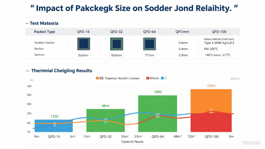
NASA simulated deep space environments to study the effect of QFN package size on solder joint reliability under thermal shock conditions. Using Weibull distribution analysis (Figure 7), QFN68 packages and QFN16–44 packages were tested. Results show that larger QFN packages have significantly shorter solder joint lifetimes compared to smaller QFN devices under identical thermal shock conditions. For deep space applications, the use of large-size QFN packages should be avoided to ensure higher solder joint reliability.
2. Influence of Body Material and Terminal Soldering Quality
The coefficient of thermal expansion (CTE) of the QFN body material has a significant impact on solder joint reliability. Studies show that the body material is the most critical factor: devices with a body CTE of 12×10⁻⁶/°C had solder joint lifetimes about 3 times longer than devices with a body CTE of 7×10⁻⁶/°C. In contrast, soldering material and terminal side-wetting quality had a smaller effect, with less than 20% difference in solder joint lifetime. For high-reliability applications, the CTE of the molding compound must be carefully considered.
3. Effect of PCB Layout on Solder Joint Reliability
As leadless devices, QFN solder joints are highly stress-sensitive. PCB layout and mounting conditions greatly affect solder joint reliability. With increasing complexity of electronic products, many PCBs require mechanical fastening into enclosures. To study this, boards with QFN devices were mounted to 4 mm-thick aluminum plates using screws and subjected to thermal cycling (-40~125 °C). Results showed that unfastened samples exhibited much higher solder joint reliability compared to screw-fastened samples. Solder joints near screw holes failed earlier, due to thermal expansion mismatch and mechanical stress. Therefore, QFN devices should be placed away from screw positions on the PCB to minimize stress and extend solder joint life.
4. Effect of Conformal Coating on Reliability
For high-reliability applications, PCBs are often coated with conformal coatings for environmental protection. Studies show that thick conformal layers significantly reduce QFN solder joint reliability under thermal cycling (-55~125 °C).
- Uncoated QFN solder joints: lifetime 2,000–2,500 cycles
- Coated QFN solder joints: lifetime 300–700 cycles
Further studies compared polyurethane coatings vs. acrylic coatings. Results showed polyurethane provided higher solder joint reliability than acrylic. Cracks in acrylic-coated joints originated at the joint root, with longer crack lengths and higher crack counts compared to uncoated samples. Researchers concluded that acrylic coatings induce additional stress under thermal cycling due to coating accumulation under the package body, accelerating solder joint crack initiation and propagation.
Therefore, when using conformal coatings on PCBs with QFN devices—especially larger packages—comprehensive testing is required to avoid adverse effects on solder joint reliability.
5. Key Design Factors Affecting QFN Board-Level Solder Joint Reliability
Board-level reliability studies show that the target solder joint height after assembly should be 2–3 mils, which is critical for improving QFN solder joint performance.
To enhance reliability, both device selection and PCB design must be optimized:
- Choose smaller package sizes, with smaller die area and thickness, and larger lead pitch.
- Follow IPC-7093 requirements and reduce PCB thickness where possible.
- Minimize thermal fluctuations and avoid PCB warpage, which introduces extra stress on QFN solder joints.
By optimizing package size, body material, PCB layout, conformal coating, and assembly design, QFN solder joint reliability can be significantly improved for high-reliability applications.